
What Is the Best Magnetic Angle Sensor?
Choosing the best Magnetic Angle Sensor depends on the machine, environment, and required accuracy. No single sensor fits every application. A compact robotic joint may need fast response and low electrical noise. A steering system may require stable readings across vibration, heat, and moisture. These differences make careful comparison more valuable than relying on impressive specifications alone.
Magnetic Angle Sensor technology measures rotational position without direct mechanical contact. This design can reduce wear, especially in motors, valves, industrial controls, and automotive assemblies. However, performance depends on magnet alignment, sensing distance, resolution, linearity, temperature stability, and signal interface. A sensor rated for high resolution may still perform poorly if the magnet sits off-center. Small installation errors can create visible position drift. The choice matters.
This guide compares common magnetic sensing approaches through practical engineering criteria. It considers accuracy, repeatability, response speed, installation tolerance, durability, and total system cost. Datasheets provide essential evidence, but real-world testing remains important. Bench results may change when nearby steel parts distort the magnetic field. Not always obvious. Experienced engineers should verify readings under expected temperature, vibration, and load conditions. We will also examine trade-offs between Hall-effect, anisotropic magnetoresistive, tunnel magnetoresistive, and integrated magnetic encoder designs. The best option is not necessarily the newest or most expensive. It is the sensor that delivers dependable angle data within the actual operating conditions. Even this approach has limits, because incomplete specifications and changing system requirements can influence the final decision.
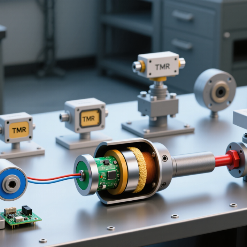
Define Magnetic Angle Sensors: Hall, AMR, GMR, and TMR Technologies
What Is the Best Magnetic Angle Sensor?
A magnetic angle sensor converts a rotating magnetic field into an electrical angle signal. The best choice depends on accuracy, speed, temperature, and mechanical space. Hall sensors detect changes in magnetic flux, usually across a sensing element. They are robust, affordable, and tolerant of moderate air-gap variation. However, their sensitivity and angular precision can be limited in demanding motion-control systems.
AMR sensors measure resistance changes as the magnetic direction changes relative to the sensing material. They often provide stable, detailed angle readings with simple signal processing. GMR sensors use layered magnetic materials and usually offer higher sensitivity than Hall or AMR devices. TMR sensors add a magnetic tunnel junction, delivering very high sensitivity and low electrical noise. That advantage can expose stray magnetic fields, imperfect magnet placement, and temperature drift. In practical testing, a sensor can perform well on the bench but lose accuracy near a motor. My early design reviews often underestimated this issue.
Tips: Match the sensor to the real magnetic environment, not only the datasheet. Check the magnet’s diameter, air gap, axial offset, and rotation speed. Calibrate across the full temperature range. Use shielding when nearby steel or current-carrying wires disturb the field. Hall suits rugged, cost-sensitive designs. AMR fits balanced precision. GMR and TMR suit compact systems requiring greater sensitivity. Alignment still matters. Even advanced sensing cannot repair a poorly centered magnet.
What Is the Best Magnetic Angle Sensor? - Define Magnetic Angle Sensors: Hall, AMR, GMR, and TMR Technologies
A practical comparison of common magnetic angle-sensing technologies. Values are typical technology-level ranges and vary with sensor design, magnet geometry, calibration, temperature, and signal conditioning.
| Evaluation Dimension | Hall Effect | AMR | GMR | TMR |
|---|---|---|---|---|
| Sensing principle | Voltage generated by a magnetic field perpendicular to a current-carrying semiconductor. | Resistance changes as the angle between current flow and magnetization changes. | Resistance changes through spin-dependent scattering in multilayer magnetic structures. | Resistance changes through spin-dependent tunneling across a thin insulating barrier. |
| Typical angular measurement | Typically 0–360° with a suitable two-dimensional Hall arrangement; single-axis devices may provide limited angular information. | Commonly 0–180° per magnetic cycle; additional circuitry or sensor arrangements may be needed for unambiguous 360° measurement. | Usually 0–360° when configured as a differential bridge or angle sensor. | Usually 0–360° with a differential bridge and appropriate magnetic-field geometry. |
| Relative magnetic sensitivity | Low to medium | Medium | High | Very high |
| Typical field requirement | Often requires a comparatively stronger magnetic field, commonly in the millitesla range. | Generally requires a moderate field with stable direction and sufficient amplitude. | Can operate with lower fields than Hall sensors in many designs. | Can provide strong output with relatively weak magnetic fields, depending on device construction. |
| Typical angle accuracy after calibration | Approximately ±0.5° to ±2° | Approximately ±0.1° to ±1° | Approximately ±0.1° to ±0.7° | Approximately ±0.05° to ±0.5° |
| Resolution potential | Moderate; limited by field strength, noise, ADC resolution, and mechanical alignment. | High; suitable for precise angular measurement when temperature and magnetic hysteresis are controlled. | High to very high; high sensitivity supports fine electrical resolution. | Very high; particularly suitable for low-field and high-resolution applications. |
| Bandwidth potential | High; many devices support fast dynamic measurement. | High, subject to bridge resistance, interface electronics, and filtering. | High, with performance determined by the magnetic stack and readout circuit. | High, although low-noise amplification and filtering may be required. |
| Power consumption | Low to medium; depends strongly on bias current and integrated electronics. | Low to medium; bridge bias current is a major factor. | Low to medium; higher sensitivity can allow reduced bias levels. | Low to medium; high sensitivity can support low-power operation, but bridge bias must be managed. |
| Temperature behavior | Generally predictable; offset and sensitivity compensation may be required. | Can be affected by magnetoresistance, bridge offset, and magnetic anisotropy changes. | Requires compensation for resistance, sensitivity, and magnetic-layer temperature effects. | Requires careful compensation because tunnel resistance and magnetic properties can vary with temperature. |
| Magnetic hysteresis risk | Usually low in linear Hall elements; magnet and mechanical system can still introduce hysteresis. | Low to moderate, depending on magnetic biasing and sensor construction. | Moderate; magnetic stack design and operating field are important. | Low to moderate in optimized designs, but magnetic stability must be verified over temperature and field range. |
| Circuit complexity | Low to medium; signal conditioning and angle calculation may be integrated or external. | Medium; often needs bridge excitation, amplification, calibration, and sometimes set/reset support. | Medium to high; requires bridge readout, compensation, and careful signal processing. | Medium to high; low noise, offset correction, and temperature compensation are commonly important. |
| Typical cost level | Low | Low to medium | Medium | Medium to high |
| Best suited applications | Cost-sensitive position sensing, commutation, speed measurement, and general-purpose rotary detection. | Precision rotary position sensing, steering systems, instrumentation, and applications requiring stable analog output. | Compact motor control, automotive position sensing, robotics, and applications needing high sensitivity. | High-precision rotary sensing, compact actuators, low-field systems, robotics, and demanding industrial or automotive designs. |
| Overall selection profile | Best when simplicity, robustness, wide availability, and low cost are the main priorities. | Best when good precision, mature technology, and stable analog behavior are required. | Best when higher sensitivity and compact packaging are more important than minimum cost. | Best when maximum sensitivity, low-field operation, and high angular accuracy justify additional design complexity. |